The
THE ALL-RUSSIAN SCIENTIFIC RESEARCH INSTITUTE FOR ELECTRIFICATION OF AGRICULTURE (VIESH)
The address of
institute:
109456,
Ph.: (095)
171-19-20.
Fax: (095)
170-51-01.
E-mail: viesh@dol.ru
Department of the scientific and
technical information, patenting and marketing - (095) 171-02-74.
Fax: (095)
170-51-01
 Director:
Academician of
Russian
Academy of Agricultural Sciences, Prof., Dr. Dmitry S. Strebkov
Ph.: (095) 171-19-20.
The deputy
director on scientific work: Dr. Anatoly V.Ā Tikhomirov
Ph.: (095)
171-04-94.
The
scientific secretary: Dr. Jury M. Antonov
Ph.: (095)
171-03-57.
The chief
engineer:
Anatoly I. Antonenko
Ph.: (095)
171-02-10.
VIESH
- the State
scientific institution. A Federal research centre on power supply, electrification and automation
of agriculture, technological development and utilization of renewable and nonconventional
energy sources. The institute was founded in March, 1930.
There are 220
highly skilled experts, including 20 doctors of sciences and 70 candidates of
sciences work at the institute.
The institute
has postgraduate study and the specialized Council on public defending doctor's
and master's theses on four specialties
05.20.02
Electric technologies and electric equipment in agriculture
05.14.08 Energy installations based on
renewable energy sources
05.13.06
Automation and control of technological processes in agricultural production
05.20.01 Agriculture technologies
and mechanization
VIESH issues proceedings on power,
electrification and automation of an agriculture, methodical recommendations
and organize annual scientific and technical conferences on rural
energy and electrification.
THE BASIC DIRECTIONS OF ACTIVITY:
Ģ ĀĀ A scientific substantiation,
the forecast and strategy of power supply, electrification and
energy saving in an agriculture, non-polluting resources saving technologies, Machines systems for electrification of an agricultural
production and cattle breeding;
Ę Highly
effective electric technologies, thermal and electric equipment and automation systems for animal industries, plant cultivation, primary processing and storage electric tractors and electric
transports agricultural products;
Ę
Development of methods and systems of reliable
rural power generation and transmission
systems, electro installations operation and safety of an
electric equipment, including stand alone power systems;
Ģ ĀĀĀĀĀĀĀ ĀSystems and means for electro mechanization of
cattle breeding creation;
Ģ ĀPerspective
technologies perfection and creation of new means for uses of renewable and
nonconventional energy sources in agriculture;
Ģ ĀThe
scientific staff education and improvement of expert professional skills;
Ģ ĀĀ Foreign trade activities and scientific and technical cooperation in the
field of rural and renewable energy;
Ę Information,
consulting and implementation services
rendering.
VIESH
has subsidies:
Ę State Unitary Enterprise
the Central Experimental Design Bureau.
The address: 109456, Moscow, 1-st Veshnyakovsky
proezd, 2. Ph.:
(095) 171-02-10. Telefax: (095) 171-27-03.
Ģ State
Unitary Enterprise ½Experimental mechanical plant "Aleksandrovsky"╗.
The
address: 601600, Gagarin Street, 6, Alexandrov town, the Vladimir region.
Ph.: (09244) 627-01.
Telefax: (09244) 625-34, 616-73.
Ę
The Interbranch Scientific and Technical Center
on milking cows machine and primary processing of milk (MNTC VIESH ½Techniques
for milk production╗);
Ę
The Scientific and Technical Center on Energy saving in an
agriculture;
Ę The international UNESCO
chair ½Renewable energy and rural electrification╗;
Ę Chair of Moscow State
Agricultural Engineering University of V.P. GorjachkinÆs name ½Renewable energy
and rural electrification╗;
Ę Experimental-technological
workshops on:
ĀĀĀĀĀĀĀĀĀĀĀĀĀ -Ā PV cells and
modules pilot manufacturing lines;
ĀĀĀĀĀĀĀĀĀĀĀĀĀ - Manufacturing of
the equipment and means of automation for technological processes in
agricultural production;
ĀĀĀĀĀĀĀĀĀĀĀĀĀ - Manufacturing of the equipment for primary
processing and storage of agricultural production;
ĀĀ - Design and application of equipment for electro mechanization dairy cattle breeding;
Ā -Ā Manufacturing of
experimental lighting equipment.
The institute, the scientific and technical centers,
pilot productions of institute and Experimental mechanical plant "Aleksandrovsky" (Aleksandrov
town, the Vladimir region) under
contracts with the
agricultural both industrial enterprises and the organizations, farms and other rural commodity producers develop technologies, carry
out projects, organize technology transfer manufacturing, purchase of machines,
the equipment, installation, architectural supervision, service.
VIESH invites to cooperation on
development and manufacturing of the electrical and technical equipment.
The Chlorine ¢ FREE Technology of producing
Solar GRADE Silicon
The technology is used for
production of polycrystalline silicon of high quality for photovoltaic industry
and in the semiconductor electronics.
Chlorine-free
technology of polycrystalline silicon production
|
Initial components: ethanol and metallurgical silicon Si + 3 C2H5OH 4SiH (OC2H5)3 SiH4 As a result of realization of technology: n Cost
of polycrystalline silicon is reduced in2times up to
15dollars / kg. n Cleanliness
and quality of silicon is increased in 10 times up to 99,999 % n Manufacture
becomes ecologically safe |
Some
techno-economic statistics
Ę Basic material (metallurgical
silicon) containing 1-3%
ballast content and ethanol are available in unlimited quantaties at a low
price.
Ę Advantages of this technology:
-
you dont use chlorine compound, that is why the whole process is ecologically
safe, all procedures are carried out under a normal pressure and temperature
not higher than 300░č;
-
chemical reactions are connected only with silicon and are carried out almost
without transfer of secondary impurities, this brings down the price of
refining;
-
reactionary products dont interreact with the reactor walls, minimizing the
contamination of the final products;
-
energy expenditure is about 30 kWh in comparisson with the usual method, when
energy expenditure is about 200 kWh, this brings down the price twofold.
ĀĀĀĀĀĀĀĀĀĀĀĀĀĀĀĀĀĀĀĀ Ę The basic product is monosilane and
polycrystalline silicon of high purity.
The
high quality of monosilane and polycrystalline silicon are proved by measured
data. Specific resistivity of crystal samples is more than 10 000 ohm sm, and
the time of life ofĀ minority carriers is
about 1000 MS.
ĀĀĀĀĀĀĀĀĀĀĀ The technology allows to change the quantity
and the range of the produced goods:
Ę Polycrystalline silicon for
electronic industry;
Ę Polycrystalline silicon for
photovoltaic industry;
Ę Polycrystalline silicon for infrared
photodevice and detectors of nuclear particles;
Ę monosilane of high quality and its
mixture with hydrogen and argon;
Ę silicon dioxide of high purity;
Ę and some others.
Solar Photovoltaic Cell Round and Pseudo Square
They
are intended for the direct conversion of the solar radiation into the electric
DC current power. It is used for assembling of the solar photovoltaic modules
of wide application.
Round and pseudo square solar cells 100 x 100 mm
The technical characteristic
|
Characteristics |
Solar photovoltaic cells |
||
|
round |
Pseudo
square |
||
|
Diameter, mm |
100 ▒ 1 |
100 ▒ 1 |
|
|
Thickness, micron |
550 ▒ 150 |
550 ▒ 150 |
|
|
Square, cm2 |
77,5 |
97 |
|
|
Antireflection coating |
Pentoxide of tantalic |
||
|
Contacting metal coating |
Tin-lead alloy |
||
|
Average efficiency at the point of max power,
% |
>12 |
>12 |
|
|
Power, W |
0,7 ¢ 1 |
1 ¢ 1,4 |
|
|
Operating voltage, V |
0,4 |
0,4 |
|
Stand alone Solar
LightING System
Solar grid-independent energy supply for
street and indoor lighting.
Designed to provide lighting within the
buildings and outside using alternative sources of energy. Examples of use:
Hazardous materials warehouses, recreational facilities.
Energy is
supplied by the solar panel and by the storage battery.
The electric power supply is carried out by solar array and by storage
battery.

1 ¢solar module; 2 ¢ luminescent lamp; 3 ¢support
device; 4 ¢ sand;
5 ¢ storage battery; 6 ¢concrete foundation; 7 ¢bottom.
Advantages:
- Can function in temperatures up
to ¢20C,
- Has a broad range of
programming options,
- Long life-span without
maintenance (up to 5 years).Ā
- The timer is programmed to turn
on all bulbs at 7 pm, turns off half of them at midnight, and turns off
the rest at 5 am.
Technical characteristic
|
Power of the lamp, W |
36 (4§9) or (2§18) |
|
Power of the solar barray, W |
100 |
|
Storage battery capacity,
ampere-hour |
56 |
|
Programming parameters |
Time of switching
on and off with season changes correction |
|
The period of in-service
life |
Up to 10 |
VIESH Renewable and
Alternative Generating Technologies
Wind PV hybrid system for grid-independent
Āenergy supply:
Purpose: grid-independent energy supply for
home appliances, TV, radios, radio stations, lighting, navigational, radio
relay and weather stations. The system includes solar photoelectric and storage
batteries, which insures supply of energy when wind speeds are below
minimal.Ā The system have passed complete
factory testing and certification.
Characteristics:
|
Parameters |
Type I |
Type II |
Type III |
|
Wind
part: Rated power, W |
160 |
500 |
1000 |
|
Voltage, V |
12 |
24 |
24 |
|
Type of current |
Direct |
||
|
Rotor diameter, m |
1.6 |
2.5 |
3.3 |
|
Wind speeds, m/s |
3.5-25 |
3.5-25 |
3-25 |
|
Weight, kg |
52 |
60 |
250 |
|
Photovoltaic array Capacity, W: |
60 |
120 |
180 |
|
Type of module Number of modules Weight, kg |
FSM 36/4-č 2 11 |
FSM 36/4-č 4 22 |
FSM 36/4-č 6 33 |
|
Invertor: Rated power, W Input Voltage, V Output voltage, V |
160 12 220Ā (50Hz) |
500 24 220 (50Hz) |
1000 24 220 (50 Hz) |
|
Storage battery* Amper-hour |
100 |
200 |
460 |
* The storage battery does not enter into structure of delivery and is
to be installed by the customer.
PORTABLE hydrolift
This device can be used for water supple and irrigation of
independent or remote consumers located near to the rivers and other water
streams. It uses low potential energy of moving water and ensured capacity of
water pumping from toĀ 100 up to 1000 l/h
with stream speedĀ from 0,6 up to 3,0 m/s
and water lifting up to 25 m.
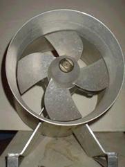
Characteristics
Capacity, l/hĀĀĀĀĀĀĀĀĀĀĀĀĀĀĀĀĀĀĀĀĀĀĀĀĀĀĀĀĀĀĀĀĀĀĀĀĀĀĀĀĀĀĀĀĀĀĀĀĀĀĀĀĀĀĀĀĀĀĀĀĀĀĀĀĀĀĀĀĀĀĀĀĀĀĀĀĀĀĀĀĀ 100
÷ 1000
Head, m ĀĀĀĀĀĀĀĀĀĀĀĀĀĀĀĀĀĀĀĀĀĀĀĀĀĀĀĀĀĀĀĀĀĀĀĀĀĀĀĀĀĀĀĀĀĀĀĀĀĀĀĀĀĀĀĀĀĀĀĀĀĀĀĀĀĀĀĀĀĀĀĀĀĀĀĀĀĀĀĀĀĀĀĀĀĀĀĀ 10
÷ 25
Steam speed ĀĀĀĀĀĀĀĀĀĀĀĀĀĀĀĀĀĀĀĀĀĀĀĀĀĀĀĀĀĀĀĀĀĀĀĀĀĀĀĀĀĀĀĀĀĀĀĀĀĀĀĀĀĀĀĀĀĀĀĀĀĀĀĀĀĀĀĀĀĀĀĀĀĀĀĀĀĀĀĀ 0,6
÷ 3,0
Rotor diameter, mm ĀĀĀĀĀĀĀĀĀĀĀĀĀĀĀĀĀĀĀĀĀĀĀĀĀĀĀĀĀĀĀĀĀĀĀĀĀĀĀĀĀĀĀĀĀĀĀĀĀĀĀĀĀĀĀĀĀĀĀĀĀĀĀĀĀĀĀ 275
Weight, kg ĀĀĀĀĀĀĀĀĀĀĀĀĀĀĀĀĀĀĀĀĀĀĀĀĀĀĀĀĀĀĀĀĀĀĀĀĀĀĀĀĀĀĀĀĀĀĀĀĀĀĀĀĀĀĀĀĀĀĀĀĀĀĀĀĀĀĀĀĀĀĀĀĀĀĀĀĀĀĀĀĀĀĀ 10
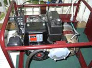
the AUTOMATED power SUPPLY
SYSTEM
It is intended for uninterrupted supply of stand-alone consumers by a
heat and electric energy.
Structure of the complete set:
internal-combustion engine (JCE) with the motor-generator on the first chassis
and the electronic block with 4 batteries on the second chassis;50 l balloon
with liquid gas; the water heat exchanger.
Features:
Ę Periodic mode of
JCE operation.
Ę Use of the dc
motor-generator for accumulation of the electric power in batteries and JCE
start-ung-up from batteries.
Ę Feed of load
through the electronic block.
Ę Automatic JCE turn
on and off according to the batteries chargeĀ
Ę Gas
fuel use for JCE.
Ę Output voltage sine
wave form distortions absence.
Ę JCE overload
protection.
Ę Exhaust
gases heat use for hot water preparation.
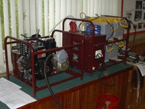
General view of an stand-alone power supply system
|
|
|
|
Gas electric Internal Combustion Engine
Generator |
The electronic block with
storageĀ batteries |

ĀĀĀĀĀĀĀĀĀĀĀĀĀĀĀĀĀĀĀĀĀĀĀĀĀĀĀĀĀĀĀĀĀĀĀĀĀĀĀĀĀĀĀĀĀĀĀĀĀĀĀĀĀ
Characteristics
|
ĀOutput power, kW: ĀĀĀĀĀĀĀĀĀ ĀĀĀĀ Electric nominal |
|
|
2 |
|
|
Electric peak |
8 |
|
Thermal ĀĀĀĀĀĀĀĀĀĀĀĀĀĀ |
2,5 |
|
Kind of fuel ¢ gas propan butane gas mixture |
|
|
Output voltage 50 Hz 204 ¢ 232 V |
|
|
Capacity of the motor-generator, W: |
|
|
ĀĀĀĀĀ In a mode of the
electromotor |
1000 |
|
ĀĀĀĀ In a mode of the generator |
1500 |
|
Voltage on the motor-generator, V |
|
|
ĀĀĀĀ In a mode of the
electromotor ĀĀĀĀĀ |
up to 48 |
|
ĀĀĀĀĀ In a mode of the generator |
up to 57 |
|
Capacity of one batteries, A▪h |
100 |
|
Gas fuel consuption, l/hour |
1 |
|
Service life, hour |
6000 |
|
Assumed outdoor temperature, ░č |
0 ¢ 45 |
|
AssumedĀ
humidity, % ĀĀĀĀĀĀĀĀĀĀĀĀĀĀĀĀĀĀĀĀĀĀĀĀĀĀĀĀĀĀĀĀĀĀĀĀĀĀĀĀĀĀĀĀĀĀĀĀĀĀĀĀĀĀĀĀĀĀĀĀĀ Āup to 80 |
up to 80 |
|
ChassisĀ dimension, mm, no more |
550´450´420 |
|
Weight without batteries and a gas container, kg |
70 |
ĀĀĀĀĀĀĀĀĀĀĀ ĀAt consumption of 3 kW▪h/day 50 liters
gas container provides operation during15 days, and Internal
Combustion Engine being in operation 3,5 h/day, will serve without
repair approximately about 5 years.Ā
Resonant Single-Wire
Electric power transmission System
Is
intended for electrical power supply of customers by transmission of the
electric power on a single-wire line.
The
principle of system operation in based on usage of two resonant circuits with
frequency
0.5-50 kHz and single-ware line between contours this system, having voltage of
a lineĀ 1-110 kVĀ and operating in a resonant mode had been
proposed 100 years ago by N. Tesla. The transmission of electrical energy in an
open circuit line uses capacity current and displacement currents, therefore
JouleÆsĀ losses on heating of a conductor
in a line are insignificant.
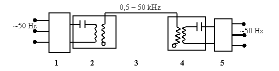
1.Frequency converterĀĀ
2.Resonance circuit of step-up transformer 3. Single-Wire line
4.Resonance circuit of step-down transformerĀ
5. Rectifier unitĀ 6. Load
Any conducting material for example,
iron wire or another conducting medium, like a water can be used as wave guide
for electromagnetic energy flow from generating station to receiving
apparatus.ĀĀĀ
There were designed special devices and
converters for adapting of this system to the common ones. These devices are
placed at the end and at the beginning of this single-wire lineĀ and allow to use in input and outputĀ standard equipment and of alternating current
devices.
Using
this system:
-
You
can reduce the flow of nonferrous metal tenfold;
-
You
can reduce expenses and energy losses.
Results of experiment of the single-wire electrical system with 20 kW
electric power
|
On-load
power Current
of the load Voltage
of the load |
20,52 kW 54 amp 380 V |
|
Voltage of the
lineĀĀĀĀ |
6,8 kV |
|
Frequency of the
line |
3,4 kHz |
|
Diameter of the
wire of the line |
80 micron/1mm |
|
Length of the line |
6 m/1700 m |
|
Maximal effective
current density |
600 A/mm2 |
|
Maximal specific
electric power |
4 MW/mm2 |
|
|
|
|
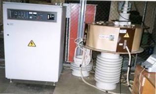
Testing of 20 kW, 10 kW resonant electric power transmission system |
Frequency converter and step-up resonant Tesla transformer |
Possible application of
resonant single-wire electric grid:
1.
Energy supply to farms and villages
2.
Single-trolley and single cable conductors hybrid public transportation
3.
Innovative single electrode electric technological devices and plasma
generators: electric cultivators, waste water decontamination, ozone
production, veterinary plasma coagulators and scalpels.
Advantages of the resonance method for energy transmission:
1.
Energy is being transmitted through reactive capacitive current in
resonance mode of operation. That makes it more difficult to steal the energy
from the utilities
2.
Copper and aluminum consumption in the wire can be reduced tenfold
3.
Steal wires with copper surface layer of .1 mm are not worth enough to be
stolen for resale as scrap metal.
4.
Energy loss in a single wire power line is low and energy can be
transmitted over long distances
5.
Short circuits are impossible in a single wire cable and so it can not
cause fire.
Thermal Conversion Plants for Manufacturing
of Fluid Fuels from Plant Biomass AND ORGANIC WASTES
Ā
Conversion plants are designed
within the new energy supply and environment protection concept based on the
use of local renewable energy sources and bio-fuels. Plant biomass, mainly in
the form of agricultural and wood processing wastes, is one of these energy
sources.
The major
application of biofuels produced by thermal conversion is cogeneration of heat
and power (CHP) using diesel engine and gas turbine based on electric power
plants and boilers in the range of 10 kW to 100 MW.
Production of gaseous and liquid
phase bio-fuels by fast pyrolysis is one of the most demanded thermal
conversion technologies insuring maximum use ofĀ
not only plant biomass but also low-calorie fossil fuels (lignite, shale
fuels, peat coal, vat residue, etc.), municipal organic wastes, agricultural and
wood wastes, as well as dedicated biomass produced by sort rotation coppices
(SRC) technique.
Fast pyrolysis is the process of
organic matter decomposition by high-rate heating to achieve a temperature at
which the yield of desired products is maximal. The optimal temperature is
determined by the upper condensed-phase limit for particular organic
components.
The technological parameters of fast
pyrolysis process, as well as the composition and quantity of manufactured
products, shall be specified prior to design and dimensioning ofĀ conversion plants for particular kinds of
solid or liquid feedstock.
The high-rate heating provides
minimum energy dissipation into the environment and maximum decomposition of
organic materials followed by vaporisation of the products. The heating time
shall be as short as possible to prevent possible undesirable changes of
chemical composition and structure of a processed material. The output of a
fluid (liquid and gaseous) fuel is determined by the organic fraction content
and is, normally, not less than 50%.
The solid fraction is composed of
non-organic compounds (ash) and thermally stable organic products such as char
and cross-linked polymers. The yield of char, which is usually less compared
with other biomass thermal conversion methods, is mainly determined by the
share of lignin in the feedstock being processed.
High temperature vaporous products
of the thermal decomposition are fed to a condenser to form the so-called
ōbio-oilö (i.e. the liquid product fraction). It is a combustible product
having substantially (about 20%) higher specific heating value than that of the
feedstock it is made of. The other part of the decomposed and vaporised
organic matter, which is non-condensable at temperatures close to normal
conditions, constitutes the gaseous fuel fraction composed of non-organic
(mainly, carbon oxides
and water) and low-molecular organic compounds, such as methane, ethane, etc. This fuel fraction can
be combusted in the pyrolysis reactor or/and utilised as a motor fuel of diesel
engines operating in the gas-and-diesel mode. Fluid fractions of plant biomass
pyrolysis products are applicable as an environmentally safe substitution for
conventional boiler fuels (black oil and natural gas). Blending into motor
fuels is one of the other promising commercial applications of bio-oil today.
In pyrolysis conversion reactors,
plant biomass can be heated either by electric heaters or/and burners fuelled
with a part of products (liquid or/and gaseous) that the conversion plant
generates itself. Typical energy consumption of the conversion plant is 5% to
10% of the total calorific power of the fuels produced. (In fact, it is nearly
proportional to the moisture content of a feedstock.)
The major features of the process
are:
-
high
conversion ratio of organic feedstocks,
-
compact
reactor design,
-
low
energy loss,
-
relatively
low cost of heat and power generated from plant biomass pyrolysis products.
In the All-Russian Research
Institute for Electrification in Agriculture (VIESH), a pilot conversion plant
for manufacturing of fluid fuels from wood sawdust and other plant wastes has
been developed in the frame of the contract from the RF Ministry of Power. The
plant is designed to produce more than 500 kg/day of fluid fuels (both liquid
and gaseous).
Following are the block diagram of
technological process and the layout of the plant, along with a short
description of the technological process.
![]()
![]()
![]()
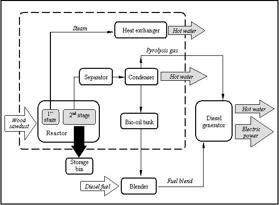
Block Diagram of Technological Process
Wood sawdust or other crushed
organic material, separated from possible extraneous objects, is fed into
reactor comprising two stages of thermal conversion. In the first stage
section, moisture is extracted from the plant biomass feedstock. The latter is
then directed to the pyrolysis stage where it is decomposed to mainly vaporous
products. A part of the decomposition products (char) that can not be vaporised
within the operating temperature range is taken out of the reactor and is
collected in a storage bin. In the separator, the vaporised products of thermal
decomposition are purified of solid micro-particles, and in the condenser, they
are cooled to form the liquid fuel fraction ¢ bio-oil. The non-condensable
fraction, pyrolysis gas, is fed to a diesel engine set operating in
gas-and-diesel mode to generate electric power, while the liquid fraction is
collected in the bio-oil tank.
Bio-oil can be used as boiler fuel
or blended into conventional diesel fuel fed to the diesel engine. This fuel
blend is, normally, comprises about 5% of bio-oil but its share can be
increased up to 15%, if necessary. Hot water
vapour and heat energy produced
as a result of the
thermochemical process is utilised in heat exchangers for local heating and hot
water supply.
The pilot plant manufactured at the
(VIESH) has been tested with different kinds of feedstock, such as wood chips,
wood sawdust, peat coal, lignite, rice husks, wastes of coffee extraction, etc.
Following is the typical product distribution for wood sawdust pyrolysis
process carried out at medium temperatures of 450 ░C to 550 ░C:
|
Product fraction |
Yield (mass %) |
|
Char |
15
to 20 |
|
Bio-oil |
40
to 60 |
|
Pyrolysis
gas |
15
to 40 |
|
|
|
|
|
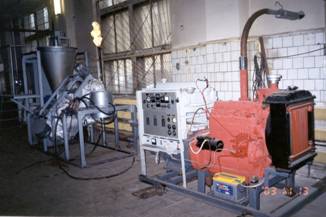
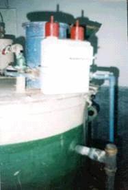
Layout
of pyrolysis plant for liquid and gaseous fuels production and 30 kW
dieselgenerator set.ĀĀ |
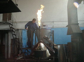
Testing of equipment for biomass conversion info
liquid and fuel. Capacity 1 t/day |
|
Physicochemical
properties of the products:
Physicochemical
properties of liquid fraction make it
applicable as oven fuel. It is also can be modified or/and blended into
conventional oil-derived products to form motor fuels.
Non-condensable gas
formed by low-molecular products (up to 30% methane, ethane, propane, hydrogen,
carbon oxides) can be effectively applied as either a furnace fuel or motor
fuel for internal combustion engines for heat and power co-generation.
Pyrolysis charÆs physicochemical properties are similar to those of conventional char
traditionally used not only for as
fuel but also in medicine, steel industry, etc.
One ton of wood
sawdust yields about 500 kg of liquid and gaseous fuels.
The payback period of
the plant is 3 years.
VIESH is ready to
enter into contracts to supply plant biomass pyrolysis plants having a
performance rate of 1 ton to 2 tons of feedstock a day. Delivery time is from 6
to 8 months.
BIOGAS INSTALLATIONS
Are
intended for non-polluting processing of organic waste with obtaining of
gaseous fuel - biogas.
PhylumÆs
of installations:
BGI ¢ 2,0 ¢ for family farms for processing of a manure from 3
conditional heads.
BGI ¢ 25 ¢ for farms (25 heads)
BGI ¢ 50 - for farmer and part-time farms (45-50
heads).
BGI ¢ 150 ¢ retrofit for processing of a manure of farms (400 heads).
BGI ¢ 500 ¢ base installation for processing of a manure 24000
heads/years.
|
BGI ¢
2,0 |
BGI ¢ 150 |
|
|
|
|
|
Model BGI ¢
500 |
Characteristics
|
Type of installation |
Quantity and volume of reactors, m3 |
Kind of processed raw material |
Productivity on initial manure, tons/day |
The general output of biogas, m3 / day |
|
BGI ¢ 2,0 |
1´2,0 |
Cattle manure |
0,1 |
1,5 |
|
BGI ¢ 25 |
1´25 |
Manure of pigs |
1,5 |
20 |
|
BGI ¢ 50 |
2´50 |
Manure of pigs |
3,0 |
40 |
|
BGI ¢ 150 |
2´150 |
Cattle manure |
25 |
300 |
|
BGI ¢ 500 |
4´125 1´500 |
Cattle manure Manure of pigs |
40 100 |
400 450 |
.